CV Joints - Disassembly and re-assembly
Click any image to enlarge
CV joints need stripping?
I had not intended to cover the removal and re-fitting of constant velocity joints (CV) but the MOT
inspector thought other wise. Our T25 failed the MOT due to split CV gaiters. Quite a simple job - no. Well
it should have been except that a previous owner had mashed the majority of the bolts holding the drive
shaft in place. This is quite typical though and normally easily rectified on a T2 but on a T25
the outer joints are situated inside the suspension arm. This meant that we could not get at the
bolts with grips or a chisel. The final solution (2 days of trying) was to weld a socket onto the
head of the damaged bolts. Not the most technical of solutions but it worked. The drive shafts are held in place by 6-off
M8x50mm bolts at each joint. T2 (Bay Windows) and T25 share the same CV joints and gaiters. The securing bolts
normally have a T40 Torx head or 6mm Allen heads. Before trying to remove, clean the head of the bolts to make sure of positive
engagement with the Torx or Allen bit. The bolts have a habit of filling up with oil, grease and dirt and
if they are not cleaned, will easily round off making removal difficult.
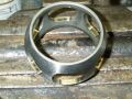
Once the joint is off?
Once the joint is off, hold it firmly in the middle using a vice. Pull back the rubber gaiter to expose the joint. Remove as much grease
as possible - it just makes the work easier. Mark the outer edge of each part of the joint with a scriber for later reference.
Remove the securing "C" clip using a pair of pointed pliers. At this point
the joint has a tendency to fall apart so make sure the 6 ball bearing don't fall under the bench to be lost for ever. Keep the parts from
each joint separate. Once the ball bearings are removed the outer and middle part of the joint will slide
off (or fall in my case).
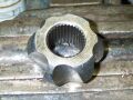
The inner joint knuckle part of the joint is a very tight fit onto the splined drive shaft.
Use a copper drift and knock the inner joint knuckle off before removing the old CV gaiter. We changed all of the 4 gaiters even
though only 2 has split as we thought it was false economy once the drive shaft was off the van. Prices for the gaiter
varied from Ł5- Ł8 with the most expensive containing all new bolts plus a tube of
the correct grease.
Clean (we used a Paraffin bath for cleaning) all of the components and examine for wear. The ball bearings should be bright and un-marked. Wear on the 3 parts of the joint
will show up as polished or rough areas depending on which part as each part differs in hardness and wears
differently to each other. As we had to change the 4 gaiters we were able to see differing amounts of wear on the 4 joints but
as they had not been making any noises before removal (and they were still full of grease) we decided to re-use all the 4 joints.
Its up to you at this point. If our van was worth much more then we would have probably changed 2 of the 4 joints.
Re-assembly.
 Reassemble of the joint is the same if you are using a new joint or re-using the existing joint. Smear a small
amount of Molybdenum grease on the inside lip of the new gaiter to ease fitment. Now for the difficult part! The inner knuckle
joint will have a chamfer on its inside edge. This is the edge that goes onto the shaft. The chamfer helps to position the
knuckle on the shaft. To confuse things, a number of the joints had chamfers on both ends but one end was always dished slightly towards
its outer edge. The dished edge should always be towards the inside of the joint. The opposite
side will be flat to enable the "C" clip to seat correctly. If you had marked all the components then you will have no need for this
explanation. We only thought of the scriber technique later and had to work it out the hard way.
Reassemble of the joint is the same if you are using a new joint or re-using the existing joint. Smear a small
amount of Molybdenum grease on the inside lip of the new gaiter to ease fitment. Now for the difficult part! The inner knuckle
joint will have a chamfer on its inside edge. This is the edge that goes onto the shaft. The chamfer helps to position the
knuckle on the shaft. To confuse things, a number of the joints had chamfers on both ends but one end was always dished slightly towards
its outer edge. The dished edge should always be towards the inside of the joint. The opposite
side will be flat to enable the "C" clip to seat correctly. If you had marked all the components then you will have no need for this
explanation. We only thought of the scriber technique later and had to work it out the hard way.
 Next, place the inner knuckle inside the middle piece of the joint.To do this you have to position the inner knuckle at 90°
to the middle joint. Once inside rotate the inner knuckle back. Now push each ball bearing into the recesses in between the 2 joints
from the outer edge. The balls will snap into position but be carefully as they will fall out if the joint is moved. The only
difference we could find on the middle part of the joint was that one edge was thinner than the
other. The thin edge always went to the inside of the joint. I can see no reason why the middle section of the joint would be handed
but we always re-assembled as we found.
Next, place the inner knuckle inside the middle piece of the joint.To do this you have to position the inner knuckle at 90°
to the middle joint. Once inside rotate the inner knuckle back. Now push each ball bearing into the recesses in between the 2 joints
from the outer edge. The balls will snap into position but be carefully as they will fall out if the joint is moved. The only
difference we could find on the middle part of the joint was that one edge was thinner than the
other. The thin edge always went to the inside of the joint. I can see no reason why the middle section of the joint would be handed
but we always re-assembled as we found.
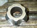
 Now this is the section were you need 3 pairs of hands. The assembled Inner and Middle section
of the joint have to be slid into the outer knuckle whilst still keeping all the ball bearings in place. Hold the assembled section at 90° to the Outer Knuckle and drop
the assembled section into the grooves in the outer knuckle. Once in, rotate back around 90°. To rotate takes a bit of fiddling
but as soon as you do it, you will know what you are trying to achieve. The CV joint is an extremely well designed and tight tolerance
piece of engineering. The joint may feel loose but each part is in close contact with each other and the movement between the
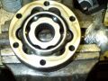
4 parts of the joints is all in the design. To check that the joint is correctly assembled, the thick sections of the inner knuckle
should be opposite thin section in the Outer Knuckle as shown in the picture. At this point, you should be able
to hold the inner knuckle and rotate the outer knuckle in all directions with ease. If the joint is stiff or
will only move in one direction then a mistake in assembly has been made.
Now this is the section were you need 3 pairs of hands. The assembled Inner and Middle section
of the joint have to be slid into the outer knuckle whilst still keeping all the ball bearings in place. Hold the assembled section at 90° to the Outer Knuckle and drop
the assembled section into the grooves in the outer knuckle. Once in, rotate back around 90°. To rotate takes a bit of fiddling
but as soon as you do it, you will know what you are trying to achieve. The CV joint is an extremely well designed and tight tolerance
piece of engineering. The joint may feel loose but each part is in close contact with each other and the movement between the
4 parts of the joints is all in the design. To check that the joint is correctly assembled, the thick sections of the inner knuckle
should be opposite thin section in the Outer Knuckle as shown in the picture. At this point, you should be able
to hold the inner knuckle and rotate the outer knuckle in all directions with ease. If the joint is stiff or
will only move in one direction then a mistake in assembly has been made.
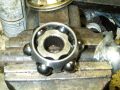
Fitting Joint to Drive shaft.
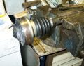 The hard work has been completed and all that is required is to position the joint onto the drive shaft. Line up the splines on
the inner knuckle with the splines on the drive shaft. The chamfer on the inner knuckle will allow it to travel a short distance
up the shaft. Once sure the splines are lined up, re-fit by hitting the inner joint using a copper drift until the "C" clip groove on
the drive shaft can be seen. When hitting the joint, get an accomplice to hold the joint together to stop the ball bearings
from falling out. Fit a new "C" clip and apply molybdenum grease to all areas of the joint. VW state that each joint should be filled
with 90 grams of grease. Slide the gaiter over the joint and secure the gaiter using a clip or large cable tie. Job Done.
The hard work has been completed and all that is required is to position the joint onto the drive shaft. Line up the splines on
the inner knuckle with the splines on the drive shaft. The chamfer on the inner knuckle will allow it to travel a short distance
up the shaft. Once sure the splines are lined up, re-fit by hitting the inner joint using a copper drift until the "C" clip groove on
the drive shaft can be seen. When hitting the joint, get an accomplice to hold the joint together to stop the ball bearings
from falling out. Fit a new "C" clip and apply molybdenum grease to all areas of the joint. VW state that each joint should be filled
with 90 grams of grease. Slide the gaiter over the joint and secure the gaiter using a clip or large cable tie. Job Done.
Nearly there.
When refitting the drive shaft to the van, cover both joints with a plastic bag and remove just before fitting. On the T25,
the outer joints as I mentioned are situated inside the suspension arm. When I was fitting the inner joint to the gearbox,
the outer joint dropped down and became covered in dirt and had to be re-stripped and cleaned! This is why I used the plastic bags
the second time plus I cleaned all the areas around the joint.
Conclusion
The first joint was difficult to strip and reassemble as there is a technique of putting the joint back together and a lot of the assembly is
done by feel. If the joint does not feel like it is sliding together and you are having to use force then stop and start again. Once you have completed
one joint, the other joints can be dismantled and re-assembled in a fraction of the time taken the first time. I would always
advise to replace the "C" clip and location bolts. Even though the joint in the pictures had evidence of wear, the wear
had not cut though the case hardening of the joint which extends around 0.5mm into the surface of each part. The joint has started
to wear and as the wear starts it will accelerate faster but I am sure that the joints have many more thousands of miles left in them! (I hope).
Home
',500,388))
 Reassemble of the joint is the same if you are using a new joint or re-using the existing joint. Smear a small
amount of Molybdenum grease on the inside lip of the new gaiter to ease fitment. Now for the difficult part! The inner knuckle
joint will have a chamfer on its inside edge. This is the edge that goes onto the shaft. The chamfer helps to position the
knuckle on the shaft. To confuse things, a number of the joints had chamfers on both ends but one end was always dished slightly towards
its outer edge. The dished edge should always be towards the inside of the joint. The opposite
side will be flat to enable the "C" clip to seat correctly. If you had marked all the components then you will have no need for this
explanation. We only thought of the scriber technique later and had to work it out the hard way.
Reassemble of the joint is the same if you are using a new joint or re-using the existing joint. Smear a small
amount of Molybdenum grease on the inside lip of the new gaiter to ease fitment. Now for the difficult part! The inner knuckle
joint will have a chamfer on its inside edge. This is the edge that goes onto the shaft. The chamfer helps to position the
knuckle on the shaft. To confuse things, a number of the joints had chamfers on both ends but one end was always dished slightly towards
its outer edge. The dished edge should always be towards the inside of the joint. The opposite
side will be flat to enable the "C" clip to seat correctly. If you had marked all the components then you will have no need for this
explanation. We only thought of the scriber technique later and had to work it out the hard way.)
) Next, place the inner knuckle inside the middle piece of the joint.To do this you have to position the inner knuckle at 90°
to the middle joint. Once inside rotate the inner knuckle back. Now push each ball bearing into the recesses in between the 2 joints
from the outer edge. The balls will snap into position but be carefully as they will fall out if the joint is moved. The only
difference we could find on the middle part of the joint was that one edge was thinner than the
other. The thin edge always went to the inside of the joint. I can see no reason why the middle section of the joint would be handed
but we always re-assembled as we found.
Next, place the inner knuckle inside the middle piece of the joint.To do this you have to position the inner knuckle at 90°
to the middle joint. Once inside rotate the inner knuckle back. Now push each ball bearing into the recesses in between the 2 joints
from the outer edge. The balls will snap into position but be carefully as they will fall out if the joint is moved. The only
difference we could find on the middle part of the joint was that one edge was thinner than the
other. The thin edge always went to the inside of the joint. I can see no reason why the middle section of the joint would be handed
but we always re-assembled as we found. ) Now this is the section were you need 3 pairs of hands. The assembled Inner and Middle section
of the joint have to be slid into the outer knuckle whilst still keeping all the ball bearings in place. Hold the assembled section at 90° to the Outer Knuckle and drop
the assembled section into the grooves in the outer knuckle. Once in, rotate back around 90°. To rotate takes a bit of fiddling
but as soon as you do it, you will know what you are trying to achieve. The CV joint is an extremely well designed and tight tolerance
piece of engineering. The joint may feel loose but each part is in close contact with each other and the movement between the
4 parts of the joints is all in the design. To check that the joint is correctly assembled, the thick sections of the inner knuckle
should be opposite thin section in the Outer Knuckle as shown in the picture. At this point, you should be able
to hold the inner knuckle and rotate the outer knuckle in all directions with ease. If the joint is stiff or
will only move in one direction then a mistake in assembly has been made.
Now this is the section were you need 3 pairs of hands. The assembled Inner and Middle section
of the joint have to be slid into the outer knuckle whilst still keeping all the ball bearings in place. Hold the assembled section at 90° to the Outer Knuckle and drop
the assembled section into the grooves in the outer knuckle. Once in, rotate back around 90°. To rotate takes a bit of fiddling
but as soon as you do it, you will know what you are trying to achieve. The CV joint is an extremely well designed and tight tolerance
piece of engineering. The joint may feel loose but each part is in close contact with each other and the movement between the
4 parts of the joints is all in the design. To check that the joint is correctly assembled, the thick sections of the inner knuckle
should be opposite thin section in the Outer Knuckle as shown in the picture. At this point, you should be able
to hold the inner knuckle and rotate the outer knuckle in all directions with ease. If the joint is stiff or
will only move in one direction then a mistake in assembly has been made.
) The hard work has been completed and all that is required is to position the joint onto the drive shaft. Line up the splines on
the inner knuckle with the splines on the drive shaft. The chamfer on the inner knuckle will allow it to travel a short distance
up the shaft. Once sure the splines are lined up, re-fit by hitting the inner joint using a copper drift until the "C" clip groove on
the drive shaft can be seen. When hitting the joint, get an accomplice to hold the joint together to stop the ball bearings
from falling out. Fit a new "C" clip and apply molybdenum grease to all areas of the joint. VW state that each joint should be filled
with 90 grams of grease. Slide the gaiter over the joint and secure the gaiter using a clip or large cable tie. Job Done.
The hard work has been completed and all that is required is to position the joint onto the drive shaft. Line up the splines on
the inner knuckle with the splines on the drive shaft. The chamfer on the inner knuckle will allow it to travel a short distance
up the shaft. Once sure the splines are lined up, re-fit by hitting the inner joint using a copper drift until the "C" clip groove on
the drive shaft can be seen. When hitting the joint, get an accomplice to hold the joint together to stop the ball bearings
from falling out. Fit a new "C" clip and apply molybdenum grease to all areas of the joint. VW state that each joint should be filled
with 90 grams of grease. Slide the gaiter over the joint and secure the gaiter using a clip or large cable tie. Job Done.)
)
)
)