Tappet gap adjustment
Click any image to enlarge
 The tappet clearance on air cooled VW's is critical for long engine life, performance
and fuel consumption. The tappet clearance is the distance required between the valve tip
and the valve actuator (rocker). A gap is required to allow for expansion of the valves
as the engine heats up. If no gap was allowed between the valve and the rocker, as the
valve expanded, the rocker would hold the valve off its valve seat resulting in poor
performance, poor fuel consumption and ultimately a burnt out valve. Tappet clearance is
all the more important on an air cooled engine due to the extremes of running temperature
compared to a water cooled engine. Making the gap to large though will also effect the
performance of the engine as the valve will lag behind the camshaft but it is always better
to error slightly on the upper clearance gap and have reduced performance compared to a
damaged engine.
The tappet clearance on air cooled VW's is critical for long engine life, performance
and fuel consumption. The tappet clearance is the distance required between the valve tip
and the valve actuator (rocker). A gap is required to allow for expansion of the valves
as the engine heats up. If no gap was allowed between the valve and the rocker, as the
valve expanded, the rocker would hold the valve off its valve seat resulting in poor
performance, poor fuel consumption and ultimately a burnt out valve. Tappet clearance is
all the more important on an air cooled engine due to the extremes of running temperature
compared to a water cooled engine. Making the gap to large though will also effect the
performance of the engine as the valve will lag behind the camshaft but it is always better
to error slightly on the upper clearance gap and have reduced performance compared to a
damaged engine.
Setting the tappet clearance is not difficult on a air cooled VW just adequate as the engine is a flat four and under the rear of the van
so access (especially for a camera) is not too good!!
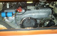 The picture shows my 1700 T4 engine but the procedure is the same for all air cooled VW engines
but please consult a workshop manual for the exact tappet setting for your engine.
The picture shows my 1700 T4 engine but the procedure is the same for all air cooled VW engines
but please consult a workshop manual for the exact tappet setting for your engine.
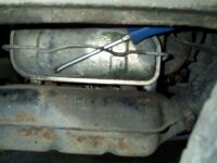
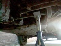 Firstly, it is much easier if the rear of the van is raised to gain better access. Make
sure that your axle stands are up to the job and place them under the rear axle tube as shown in
the picture. Never go underneath any vehicle when supported by a jack alone.
Firstly, it is much easier if the rear of the van is raised to gain better access. Make
sure that your axle stands are up to the job and place them under the rear axle tube as shown in
the picture. Never go underneath any vehicle when supported by a jack alone.
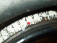 Remove the mesh cover(3-10mm bolts) to gain access to the crank shaft pulley.
Replace the white timing degree template so that you can view the position of the engine.
At the same time, highlight the Top Dead Centre (TDC) notch on the crank shaft pulley and also
make a second mark 180 degrees around from the TDC mark.
Remove the mesh cover(3-10mm bolts) to gain access to the crank shaft pulley.
Replace the white timing degree template so that you can view the position of the engine.
At the same time, highlight the Top Dead Centre (TDC) notch on the crank shaft pulley and also
make a second mark 180 degrees around from the TDC mark.
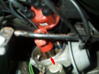 Next remove the distributor cap to view the rotor arm position. Then using a 13mm socket and 150mm extension turn the
crankshaft until the rotor arm is pointing towards the notch in the distributor body (No.1 cylinder)
and the TDC notch in the crankshaft pulley is at 0 degrees. At this position, No.1 cylinder is at
TDC and both valves are closed and the tappet clearance can be checked.
Next remove the distributor cap to view the rotor arm position. Then using a 13mm socket and 150mm extension turn the
crankshaft until the rotor arm is pointing towards the notch in the distributor body (No.1 cylinder)
and the TDC notch in the crankshaft pulley is at 0 degrees. At this position, No.1 cylinder is at
TDC and both valves are closed and the tappet clearance can be checked.
 Remove the drivers side valve cover by inserting a screwdriver between the retaining clip and the cover
and levering downwards. If you push the clip upwards, it is very difficult to get back into
place. Guess how I know??
Remove the drivers side valve cover by inserting a screwdriver between the retaining clip and the cover
and levering downwards. If you push the clip upwards, it is very difficult to get back into
place. Guess how I know??
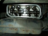 You will now be able to view the rocker assembly. The exhaust
valves are on the outside edge and the 2 middle valves are inlet valves.
The setting for the 2 are different as the exhaust valve requires more clearance as
it expands more being in the hot exhaust gas outlet than the inlet valve which is cooled by
the incoming petrol. The settings for my 1700 engine are 0.15mm for the inlet and 0.2mm for the
exhaust valves. Again, check your workshop manual. Note measurement and adjustment is taken place
with the engine cold. The best time to do the work is before the engine has been started.
You will now be able to view the rocker assembly. The exhaust
valves are on the outside edge and the 2 middle valves are inlet valves.
The setting for the 2 are different as the exhaust valve requires more clearance as
it expands more being in the hot exhaust gas outlet than the inlet valve which is cooled by
the incoming petrol. The settings for my 1700 engine are 0.15mm for the inlet and 0.2mm for the
exhaust valves. Again, check your workshop manual. Note measurement and adjustment is taken place
with the engine cold. The best time to do the work is before the engine has been started.
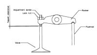
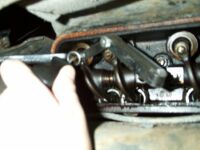 The gap is measured by inserting a feeler gauge of the correct thickness between the valve tip and the rocker arm. The feeler gauge
should be a tight sliding fit between the two. If it is not then the clearance needs to be adjusted.
Adjustment is carried out by loosening the 13mm locknut and turning the tappet screw in to
reduce the gap and out to increase the gap. This is one of those jobs were you need 2 pairs
of hands as you have to hold the feeler gauge in place, turn the screw, then tighten the nut
to lock into position. At first it seems difficult but after a bit of practice, you soon
get the hang of it. When tightening the lock nut the tappet screw usually moves so take care that
the gap has not closed up. After tightening, re-check the gap. After checking both inlet and
exhaust valves on No.1 cylinder return to the back of the van and turn the crankshaft pulley
180 degrees anti-clockwise until the rotor arm points to No.2 electrode on the distributor cap.
Again, follow the procedure for checking /adjustment on No.2 cylinder before replacing the valve
cover. After checking No.2 cylinder, the passenger side valve cover needs to be removed to
gain access to cylinders 3 and 4 and the crankshaft pulley turned anti-clockwise 180 degrees again.
No. 3 cylinder valves can now be adjusted. After adjustment, again rotate the engine 180 degrees anti-clockwise
and adjust No.4 cylinder valves.
The gap is measured by inserting a feeler gauge of the correct thickness between the valve tip and the rocker arm. The feeler gauge
should be a tight sliding fit between the two. If it is not then the clearance needs to be adjusted.
Adjustment is carried out by loosening the 13mm locknut and turning the tappet screw in to
reduce the gap and out to increase the gap. This is one of those jobs were you need 2 pairs
of hands as you have to hold the feeler gauge in place, turn the screw, then tighten the nut
to lock into position. At first it seems difficult but after a bit of practice, you soon
get the hang of it. When tightening the lock nut the tappet screw usually moves so take care that
the gap has not closed up. After tightening, re-check the gap. After checking both inlet and
exhaust valves on No.1 cylinder return to the back of the van and turn the crankshaft pulley
180 degrees anti-clockwise until the rotor arm points to No.2 electrode on the distributor cap.
Again, follow the procedure for checking /adjustment on No.2 cylinder before replacing the valve
cover. After checking No.2 cylinder, the passenger side valve cover needs to be removed to
gain access to cylinders 3 and 4 and the crankshaft pulley turned anti-clockwise 180 degrees again.
No. 3 cylinder valves can now be adjusted. After adjustment, again rotate the engine 180 degrees anti-clockwise
and adjust No.4 cylinder valves.
On completion, replace the valve cover ( always use new gaskets to prevent leaks), distributor cap
and the crankshaft pulley mesh cover before starting the engine. Task done until the next 3000 miles is up.
If at anytime you are unsure of anything always seek the help of someone that knows, rather than
risk damage to an engine.
Home
)
) The picture shows my 1700 T4 engine but the procedure is the same for all air cooled VW engines
but please consult a workshop manual for the exact tappet setting for your engine.
The picture shows my 1700 T4 engine but the procedure is the same for all air cooled VW engines
but please consult a workshop manual for the exact tappet setting for your engine.) Firstly, it is much easier if the rear of the van is raised to gain better access. Make
sure that your axle stands are up to the job and place them under the rear axle tube as shown in
the picture. Never go underneath any vehicle when supported by a jack alone.
Firstly, it is much easier if the rear of the van is raised to gain better access. Make
sure that your axle stands are up to the job and place them under the rear axle tube as shown in
the picture. Never go underneath any vehicle when supported by a jack alone.) Remove the mesh cover(3-10mm bolts) to gain access to the crank shaft pulley.
Replace the white timing degree template so that you can view the position of the engine.
At the same time, highlight the Top Dead Centre (TDC) notch on the crank shaft pulley and also
make a second mark 180 degrees around from the TDC mark.
Remove the mesh cover(3-10mm bolts) to gain access to the crank shaft pulley.
Replace the white timing degree template so that you can view the position of the engine.
At the same time, highlight the Top Dead Centre (TDC) notch on the crank shaft pulley and also
make a second mark 180 degrees around from the TDC mark.) Next remove the distributor cap to view the rotor arm position. Then using a 13mm socket and 150mm extension turn the
crankshaft until the rotor arm is pointing towards the notch in the distributor body (No.1 cylinder)
and the TDC notch in the crankshaft pulley is at 0 degrees. At this position, No.1 cylinder is at
TDC and both valves are closed and the tappet clearance can be checked.
Next remove the distributor cap to view the rotor arm position. Then using a 13mm socket and 150mm extension turn the
crankshaft until the rotor arm is pointing towards the notch in the distributor body (No.1 cylinder)
and the TDC notch in the crankshaft pulley is at 0 degrees. At this position, No.1 cylinder is at
TDC and both valves are closed and the tappet clearance can be checked.) Remove the drivers side valve cover by inserting a screwdriver between the retaining clip and the cover
and levering downwards. If you push the clip upwards, it is very difficult to get back into
place. Guess how I know??
Remove the drivers side valve cover by inserting a screwdriver between the retaining clip and the cover
and levering downwards. If you push the clip upwards, it is very difficult to get back into
place. Guess how I know??) You will now be able to view the rocker assembly. The exhaust
valves are on the outside edge and the 2 middle valves are inlet valves.
The setting for the 2 are different as the exhaust valve requires more clearance as
it expands more being in the hot exhaust gas outlet than the inlet valve which is cooled by
the incoming petrol. The settings for my 1700 engine are 0.15mm for the inlet and 0.2mm for the
exhaust valves. Again, check your workshop manual. Note measurement and adjustment is taken place
with the engine cold. The best time to do the work is before the engine has been started.
You will now be able to view the rocker assembly. The exhaust
valves are on the outside edge and the 2 middle valves are inlet valves.
The setting for the 2 are different as the exhaust valve requires more clearance as
it expands more being in the hot exhaust gas outlet than the inlet valve which is cooled by
the incoming petrol. The settings for my 1700 engine are 0.15mm for the inlet and 0.2mm for the
exhaust valves. Again, check your workshop manual. Note measurement and adjustment is taken place
with the engine cold. The best time to do the work is before the engine has been started.) The gap is measured by inserting a feeler gauge of the correct thickness between the valve tip and the rocker arm. The feeler gauge
should be a tight sliding fit between the two. If it is not then the clearance needs to be adjusted.
Adjustment is carried out by loosening the 13mm locknut and turning the tappet screw in to
reduce the gap and out to increase the gap. This is one of those jobs were you need 2 pairs
of hands as you have to hold the feeler gauge in place, turn the screw, then tighten the nut
to lock into position. At first it seems difficult but after a bit of practice, you soon
get the hang of it. When tightening the lock nut the tappet screw usually moves so take care that
the gap has not closed up. After tightening, re-check the gap. After checking both inlet and
exhaust valves on No.1 cylinder return to the back of the van and turn the crankshaft pulley
180 degrees anti-clockwise until the rotor arm points to No.2 electrode on the distributor cap.
Again, follow the procedure for checking /adjustment on No.2 cylinder before replacing the valve
cover. After checking No.2 cylinder, the passenger side valve cover needs to be removed to
gain access to cylinders 3 and 4 and the crankshaft pulley turned anti-clockwise 180 degrees again.
No. 3 cylinder valves can now be adjusted. After adjustment, again rotate the engine 180 degrees anti-clockwise
and adjust No.4 cylinder valves.
The gap is measured by inserting a feeler gauge of the correct thickness between the valve tip and the rocker arm. The feeler gauge
should be a tight sliding fit between the two. If it is not then the clearance needs to be adjusted.
Adjustment is carried out by loosening the 13mm locknut and turning the tappet screw in to
reduce the gap and out to increase the gap. This is one of those jobs were you need 2 pairs
of hands as you have to hold the feeler gauge in place, turn the screw, then tighten the nut
to lock into position. At first it seems difficult but after a bit of practice, you soon
get the hang of it. When tightening the lock nut the tappet screw usually moves so take care that
the gap has not closed up. After tightening, re-check the gap. After checking both inlet and
exhaust valves on No.1 cylinder return to the back of the van and turn the crankshaft pulley
180 degrees anti-clockwise until the rotor arm points to No.2 electrode on the distributor cap.
Again, follow the procedure for checking /adjustment on No.2 cylinder before replacing the valve
cover. After checking No.2 cylinder, the passenger side valve cover needs to be removed to
gain access to cylinders 3 and 4 and the crankshaft pulley turned anti-clockwise 180 degrees again.
No. 3 cylinder valves can now be adjusted. After adjustment, again rotate the engine 180 degrees anti-clockwise
and adjust No.4 cylinder valves.